YAESU FT-DX101D

Yaesu FT-DX101D HF/50MHz 100W SDR

Yaesu FT-DX101D HF/50MHz 100W SDR Reservation

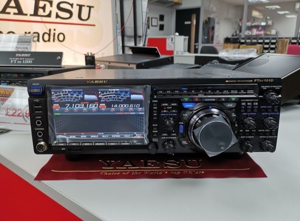
YAESU is excited to introduce a new High-Class HF/50MHz 100WTransceiver – FTDX101D and the first sample will be seen at Dayton Hamvention 2018.

The new FTDX101D is utilizing the latest SDR Technology and classified as our High-End HF line, the FTDX series, which amateurs have come to know represents quality.

A few of the remarkable features of the new FTDX101D are;

  • YAESU High-Class HF/ 50MHz 100W Transceiver
  • SDR Technology and Waterfall Display
  • Large Touch Panel precision color display
  • Active Band Monitor enables rapid band changes with LED illumination of the operating band
  • Independent control of the Main and Sub Bands allows effortless operation for the serious contester needing to move quickly between the amateur bands
  • High-Q VC Tuning Front-End
  • Main tuning dial for Main and Sub Band frequency control includes an Outer Dial for clarifier, VC tuning, fine tuning or custom settings.

As you may recall, the name “101” comes from Yaesu’s legendary-popular best seller FT-101 series. With all its strength, YAESU produced this new HF transceiver to carry on the tradition of high quality known from the original 101 series. The new FTDX101D will be certain to satisfy the variety of many amateur radio enthusiasts’ demands.
Sdr versatile tutta da scoprire

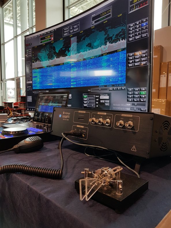
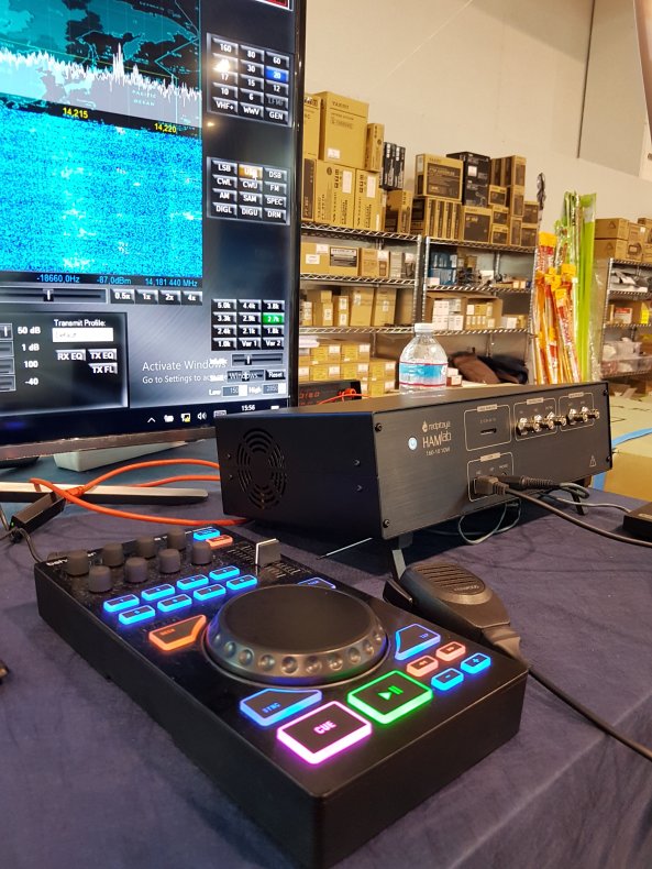
HAMLAB RED PITAYA


Red Pitaya è la ben nota piattaforma open source basata sul sistema operativo GNU/Linux, di dimensioni estremamente compatte e dotata di processore dual core ARM Cortex A9, FPGA, DDR3 RAM 512 MB, ingressi analogici, uscite analogiche, I/O digitali, porta Ethernet, slot per memorie micro SD card e via discorrendo. Red Pitaya può fare un sacco di cose ma HAMLAB ne amplia i modi di funzionamento. Con HAMLAB si può combinare la magia di una Software Defined Radio con una serie di indispensabili strumenti da laboratorio. HAMLAB è infatti SDR, oscilloscopio, spectrum analyzer, logic analyzer, network vector analyzer e molto altro. In modalità oscilloscopio dispone di due canali di ingresso con banda di 50 MHz, sampling rate di 125 Msps, input range di ± 20 volt, risoluzione di 14 bit. In modalità spectrum analyzer dispone di due canali di ingresso con banda di 62 MHz, range dinamico di -80 dBm e input noise level di -119 dBm/Hz. In modalità logic analyzer dispone di otto canali di ingresso, sampling rate di 125 Msps, livelli logici 2,5/3,3/5 volt, con decodifica dei protocolli SPI, UART, I2C. Ma di gran lunga più interessante per il mondo radioamatoriale è la modalità SDR. Copertura di frequenza in trasmissione da 1 MHz fino a 62 MHz, quindi tutte le bande 160/80/40/30/20/17/15/12/10/6 metri. Potenza di uscita TX 10 watt con stadio finale LDMOSFET. Per chi vuole “esagerare” è disponibile una versione con uscita di 100 watt. Copertura di frequenza in ricezione da 25 kHz fino a 62,25 MHz. Architettura del ricevitore direct sampling con possibilità di attivare un secondo ricevitore. Preamplificatori da 15/30 dB e attenuatori da 12/24/36 dB incorporati. Connessione diretta per un tasto morse o per un microfono con PTT. Due ingressi di antenna selezionabili via software con connettori BNC e SO-239 UHF. Disponibili come option un preselettore e un controllore con “manopolona” che semplifica le impostazioni delle differenti modalità di funzionamento del RTX. Alimentazione richiesta 12 volt 4 ampere (che salgono a 10 ampere per la versione con 100 watt output). I software supportati sono PowerSDR, HDSDR, Gqrx, GNU Radio, GNU Radio Companion e Pothos. Un laboratorio elettronico di alto livello e un RTX di alte prestazioni racchiusi in uno spazio estremamente ridotto per venire incontro a tutte le esigenze di una moderna stazione radioamatoriale. Con HAMLAB si può fare veramente di tutto. Non a caso lo slogan pubblicitario scelto per HAMLAB è “Swiss army knife for HAM radio operators”. Maggiori informazioni su http://hamlab.redpitaya.com/

Icom IC-7300 New! – Toyko HamFair 2015

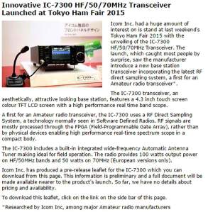
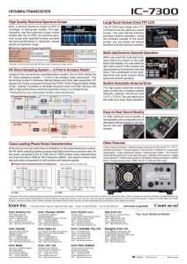
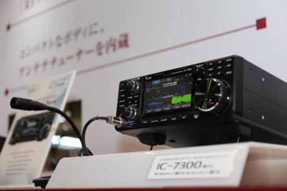
IC-7300 that Icom has been announced, in SSB / CW / RTTY / AM / FM transceiver of HF ~ 50MHz band, “IC-7300″ of 100W output, “IC-7300M” of 50W type, of 10W type “IC- 7300S “me to line up. Features are as follows.
– It is equipped with a high-performance real-time scope equipped with a practical skills
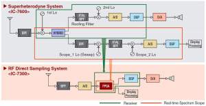
Amateur radio’s first adopted the “RF direct sampling method”
(as the main amateur radio equipment manufacturer)

The implementation phase noise characteristics that transcend the class
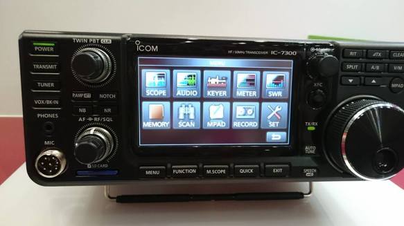
Equipped with a large color TFT LCD display that corresponds to the touch panel
– In a compact body, and a built-in antenna tuner
– Audible high sound quality is achieved.

FB_IMG_1440437510112

FB_IMG_1440437466280

FB_IMG_1440437482500

IC-7300_icom

11038007_914805078593726_7208670379565171804_n

FB_IMG_1440217110234

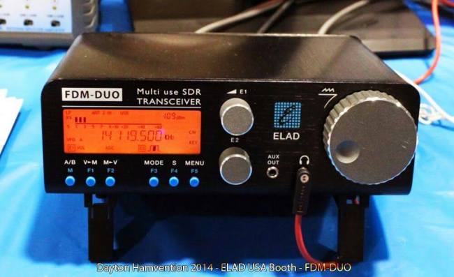
Elad FDM-DUO standalone SDR HF+6m transceiver Dayton Hamvention® 2014 Product Made in Italy

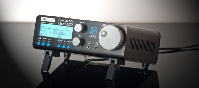
Things seem to be going the right way for SDR technology. The latest spawn from Italy – calledELAD FDM DUO – definetely got my interest; we are talking about a direct sampling full SDR transceiver for HF/6m, that can also run standalone. The closest thing to it might be the Elecraft KX-3, but that is considerably behind in technology and still manages to have one of the top recievers aroundImmagine.

The ELAD FDM-DUO recieves from 9KHz to 52MHz and covers all the amateur bands from 160m to 6m, claiming an MDS of -132dB and an BDR or +115dB @ 500Hz. Power output is only 5watt

Besides being standalone, it can also be attached to a computer so you can benefit from all the power of the SDR technology: big spectrum analizer (up to 6MHz), dual recievers, total control via their SW-2software etc.

Immagine


Here’s what makes it go:
– ADC: Linear Technology LTC2165 clocked at 122.88MHz
– DDC: Xilinx Spartan 6 XC6SLX25 FPGA + serial flash
– DDS: AD9957
– 2x STM32F4 microcontrollers


What I don’t like about it is the fact that it is not concieved as a product, but looks more as a technological demo, made entirely by engineers. The hefty pricetag (1160EUR, about US$ 1600) asks for a good user interface, useful output power and decent build quality, otherwise it will be just a stillborn novelty – interesting from a technological standpoint but not appealing to purchase and use. FDM-DUO’s kickass electronics with 100W output and a useful front panel could definetely your main station transceiver. 

FUNcube-1 Launch Date Announced

Add your thoughts here… (optional)

AMSAT-UK

AMSAT-UK and AMSAT-NL are delighted to be able to announce that they have been advised that the launch date for FUNcube-1 is now expected to be late November 2013. The date is still subject to final approval by the authorities.

The FUNcube project started back in 2009 so it is a great relief that we now have a confirmed date for lift off.

FUNcube-1 will lift off from the Yasny launch base located in the Orenburg Region, Russia on a Dnepr Launch Vehicle that will insert multiple satellites into a 600 km, 97.8º inclination sun-synchronous orbit.

FUNcube-1 is a 1U CubeSat that will provide a signal directly from a satellite in space to the classroom, and can easily be received by schools and colleges. The target audience is students at both primary and secondary levels. The information will be displayed in an attractive format and provide stimulation and encouragement for…

View original post 251 altre parole

14-30 MHz Magnetic Loop Antenna

The small magnetic loop antenna is a compact efficient antenna that is ideal for portable deployment or for limited spaces and that can be improvised inexpensively.  The antenna is essentially a tuned circuit with an inductor formed by a loop of wire measuring less than 1/4 wavelength and resonated to the operating frequency with a capacitor.  Due to its low radiation resistance and large circulating current, the loop must be constructed of a large outer diameter conductor of low resistance for best efficiency.  Typically these loops are built from coaxial cable, hardline, or copper or aluminum tubing.  These loops have a very narrow bandwidth and require a variable capacitor (and preferably a reduction drive) to be resonated at the operating frequency.  Air variable capacitors or vacuum variable capacitors are used due to the voltage on the order of several thousand volts that is developed across the capacitor.  In order to maintain the lowest possible series resistance, soldered connections and a “butterfly” or split-stator capacitor are preferred. The addition of a fixed capacitor in parallel with the variable capacitor will allow operation of this antenna on 7 or 10 MHz at reduced efficiency by Dr. Carol F. Milazzo, KP4MD

IMG_0825

Construction of a Compact and Efficient Portable High Frequency Antenna

Thank you very much for the work done Carol F. Milazzo, KP4MD

New Yaesu FTdx-1200

ftdx-1200-back-panel

1200spec

Download FTDX 1200 Brochure 

Data Format for Korean OSSI CubeSat

Add your thoughts here… (optional)

AMSAT-UK

Open Source Satellite Initiative Korean CubeSat OSSI-1Information has been released on the data format to be used by the Open Source Satellite Initiative (OSSI) CubeSat developed by Hojun Song DS1SBO.

The OSSI Data Format spreadsheet can be seen at https://docs.google.com/spreadsheet/ccc?key=0AjtQ6cJ4QOqJdGpHNnRtUWZJV0w4TTFKRU9WYTZqc3c#gid=5

OSSI-1 is planned to launch April 19, 2013 into a 575 km 63° inclination orbit on a Soyuz-2-1b rocket from the Baikonur launch facility in Kazakhstan along with the Bion-M1 satellite and the SOMP, BEESAT 2, BEESAT 3 and Dove-2 CubeSats. The OSSI VHF beacon is understood to be using 12 WPM CW.

Open Source Satellite Initiative OSSI CubeSat Wiki http://www.uk.amsat.org/?p=12231

View original post

144 MHz Halo Antenna

Construction of a Low Cost Omnidirectional Horizontally Polarized Antenna for 144 MHz


882128_10200898338965908_1090198375_o

Antenna HALO per i 144 MHz. La realizzazione di un’antenna può sembrare, alcune volte difficoltosa. Molte di queste infatti necessitano di particolari accorgimenti costruttivi che rendono l’antenna robusta e sicura alle intemperie. Non sempre però questi accorgimenti costruttivi si rendono necessari, come ad esempio quando si desidera sperimentare una antenna nuova e con forme diverse da quelle che solitamente siamo abituati a vedere.

Una di queste antenne è la HALO. Questa antenna a colpo d’occhio stupisce per la strana forma che ha, ma se la si guarda con attenzione si può vedere che non è altro che un dipolo a mezz’onda munito di Gamma Match che viene piegato in modo da formare un cerchio: questo accorgimento costruttivo riduce lo spazio occupato dall’estensione del normale dipolo, ma ne mantiene la direttività.

In pratica, piegando il dipolo in modo da formare un cerchio riduciamo lo spazio occupato dal normale dipolo quando esso, esteso, gira: questo particolare accorgimento non rende l’antenna omnidirezionale in quanto il dipolo pur avendo acquisito la forma di un cerchio mantiene la direttività, pertanto l’antenna dovrà essere orientata verso il corrispondente in modo da avere il maggior segnale possibile. Un’antenna di questo tipo si presta molto bene per l’uso mobile.